LESSON 4
Preparing your Model for 3D Printing
In this unit you will learn how to set up a 3D print job by creating a G-code file, the different parameters of a 3D print, and tips and tricks for successful prints.
Now that we have a 3D model, we have to setup the print job. The 3D model file exists on your computer simply as digital information. In order to print it, we need to slice the model into directions that the 3D Printer can follow. These directions are known as G-code and are generated by a slicing software.
When slicing a 3D model, there are several factors you can control that will influence the performance of your 3D printed object. These include object orientation, object resolution, infill percentage, object shells, and support material.
Step 1: Position the Digital Object
First we will open our 3D model (STL File) in our slicing software. When the object appears in the software, we will need to orient it on the build platform.
The position of an object on the build platform can have a dramatic impact on the end result of the print. Orientation of your print impacts print time, success, accuracy, and strength of your print. Orient your model so a flat surface is facing down on the build platform.
 Dudlee our robot showing you the correct way to orient your object on the build plate in the slicing software.
The Buildini™ prints in horizontal layers, building the object from the bottom up. As a rule of thumb: fewer vertical layers make for a stronger object that will also print faster.
Step 2: Object Resolution and Layer Height
Just like a digital photograph, a 3D printed object has a resolution. High-resolution photos are made up of very densely packed pixels that create the illusion of a crisp and smooth picture. In contrast, low-resolution photos use far fewer pixels creating an image that looks pixelated.
In 3D printing, object resolution corresponds to the layer height, which is measured in millimeters or microns. Smaller layer heights result in higher resolution objects with smooth surfaces. Small layer heights will increase print time. High-resolution objects take significantly longer to 3D print than low resolution ones. This is because of all the added layers in a high resolution object.
Larger layer heights are considered low resolution, as the print lines are visible.
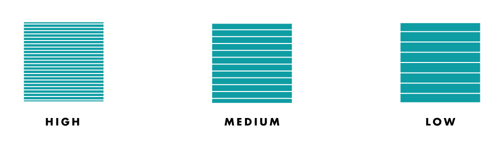 Example of low, medium, and high resolution objects.
Below is a chart with the different resolutions and the typical layer heights for these classifications.
| Resolution | Layer Height | Relative Print Time |
|---|---|---|
| Low | 0.3mm-0.4mm | Short |
| Medium | 0.2mm-0.3mm | Medium |
| High | 0.1mm-0.2mm | Long |
Step 3: Object Shells
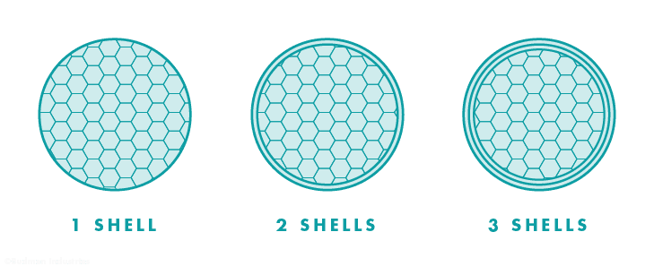
Object shells, or perimeters, are the outer layers of the print that make up the walls of your object. The more shells, the stronger your object will be. Use fewer shells when creating display items, such as sculptures. Use more shells when your 3D printed object needs to withstand heavy pressures or stress, such as mechanical parts. Adding shells will also increase the print time and use more material.
Step 4: Infill
The object infill refers to the inside structure and density of a 3D printed object.
Infill is measured in percentage. An object printed at 100% infill will be 100% solid whereas an object printed at 20% infill will create a grid structure to fill 20% of the interior space of the object. The slicing software can generate infill in several patterns. We recommend the honeycomb pattern for speed and strength.
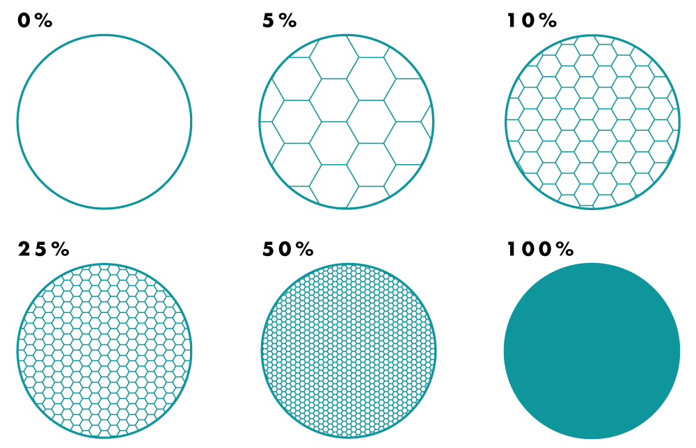 A diagram of different infill densities.
Light use and decorative objects can have a lower infill density, 5%-20%, to save time and money. Objects that need to stand up under heavy use should be printed with an infill density of 20% or higher. The denser the infill, the longer the print time.
Step 5: Support Material and Raft
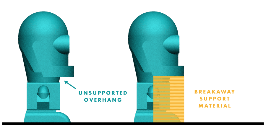
In the last module we mentioned that objects with overhangs or bridges that exceed 45° can be printed using support material. The slicing software includes an option for adding support material to these parts which is used as a scaffold to hold up these unsupported features. After printing, the support material will easily break away from your 3D printed object and can be discarded.
 Dudlee our robot showcasing an object 3D printed with support material
Some materials and 3D models can have a difficult time adhering to the build platform. In these scenarios it is helpful to use a raft. A raft is a removable latticework printed underneath an object to help with warping and bed adhesion. It creates a strong foundation for models with small features. Check the raft box within the slicing software and it will help to remedy your issue. After printing, the raft will easily break away from your 3D printed object.
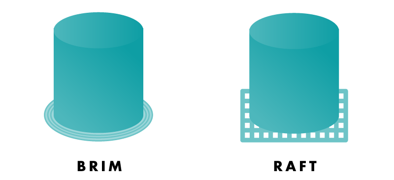 Example of an object printed with a raft.
Step 5: Slice and Save
After you have adjusted the settings to fit your printing needs, go ahead and slice your object. This will generate a G-code file. Save the G-code file to your computer or SD card. We are now ready to print with our 3D Printer.
Click here to go to the next module: 3D Printing Your Object
Vocab Words
- Build Platform: The surface where an object is 3D printed. Also called build plate or bed.
- Infill: Internal support structure of FFF printed objects; the higher the percentage of infill, the denser the object.
- Layer Height: Height of the horizontally printed layers of a 3D printed object, typically measured in millimeters or microns.
- Raft:Removable and discarded latticework of filament underneath an object to help with warping and bed adhesion.
- Slicer: Software that converts STL files or other 3D model formats into G-code files for 3D printing.
- Slicing: Process of converting a 3D model into G-code files containing fabrication instructions for a 3D printer.
- STL File: Digital file format for a 3D model, imported into a slicer to convert it to G-code.
- Support: Removable and discarded 3D printed material used to successfully fabricate overhangs, bridges, and negative space.