USER GUIDE 1
Buildini™ Anatomy
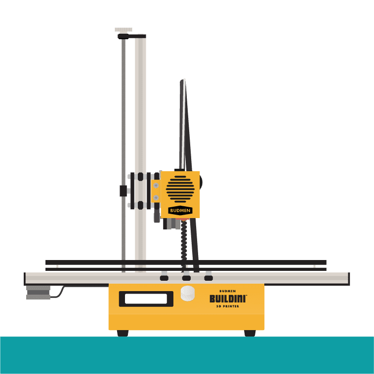
To get the most out of your Buildini™ 3D Printer it is important to become familiar with all of its components. This guide will help you understand the different parts and functions of the Printer.
EXTRUDER EXPLAINED
The Buildini™ 3D Printer uses a filament extruder to pull plastic into a heated nozzle, liquefy the polymer, and push it out through the nozzle to produce a controlled stream of material.
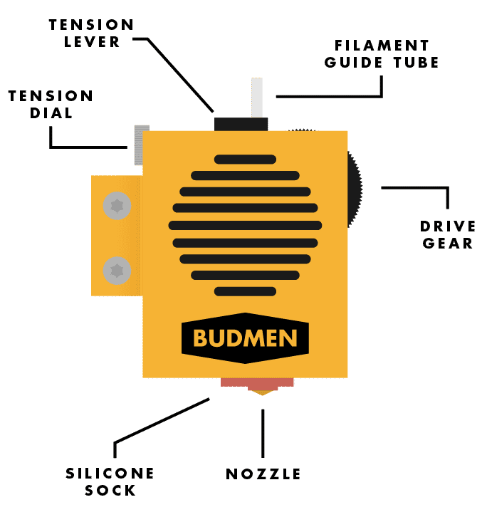 Diagram of the Extruder Exterior
The extruder consists of two main parts:
1) A Feeding Mechanism to pull in the plastic, and
2) A Hot End to melt and extrude the plastic.
The Feeding Mechanism uses a clamp to grip the filament and a moving gear to pull it into the extruder. The clamp’s grip can be adjusted using the tensioning dial on the left side of the extruder.
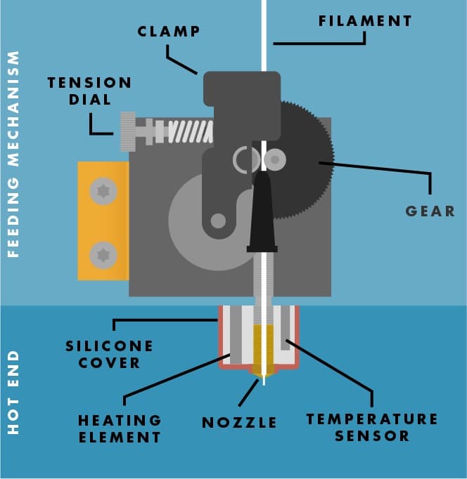 Cross-Section of the Extruder Interior
The Hot End has a heating element to melt the plastic, a temperature sensor to monitor the heat, a nozzle for precise placement of the liquid plastic, and a silicone cover to contain the heat.
BUILD PLATFORM
The build platform is the surface where an object is 3D printed.
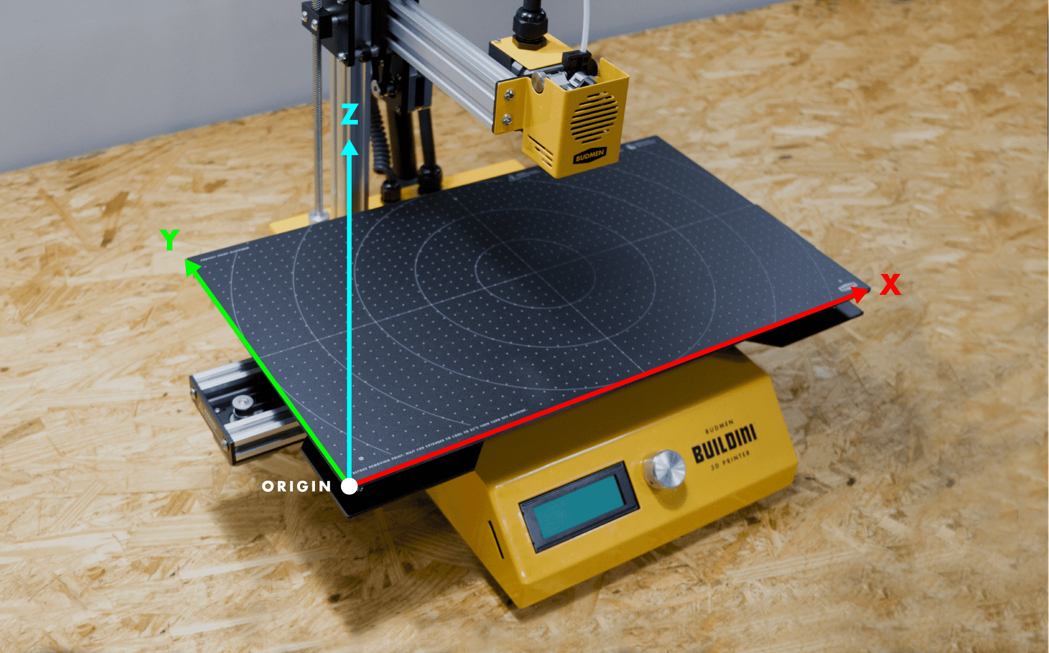 Image of build platform with Origin marked
This build platform needs to be level relative to the extruder so the object can be built on a flat surface. The Budmen Buildini™ 3D Printer build platform consists of two parts: 1) the plate, made from carbon fiber to ensure superior flatness, and 2) the build platform surface, made from a specialty polymer and can be replaced, if needed.
There are three leveling points on the surface of the build platform identified by white circles with black crosses.
Leveling the build platform is achieved by using the three leveling knobs found under these circles.
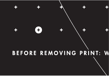 The three leveling points are identified by a white circle with a black cross.
Tightening or loosening these knobs will respectively lower or raise the build platform.
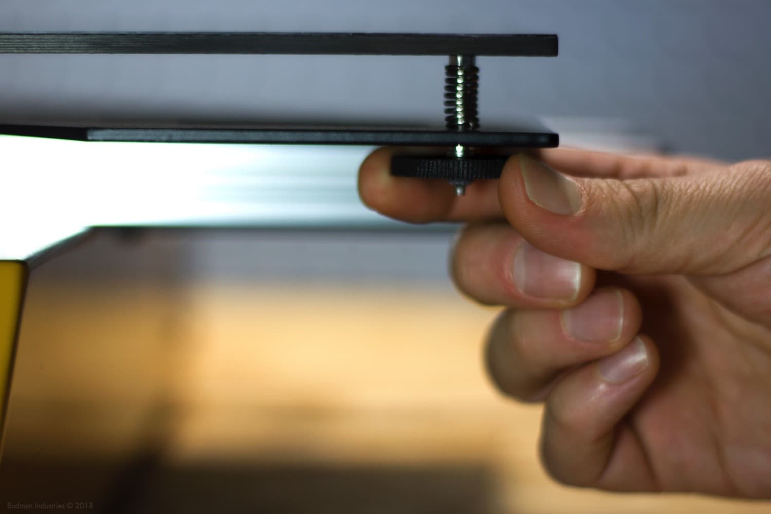 Image showing fingers on leveling knob
LCD SCREEN
The LCD Screen is how you will monitor print progress and adjust settings on your Buildini™ 3D Printer. All operations including preheating, starting print jobs, and adjusting settings are controlled through the LCD screen.
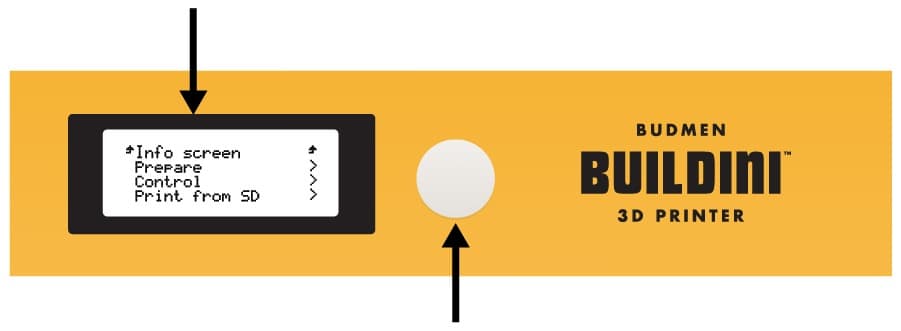 Diagram of front of Buildini™ showing LCD Screen and Spin-n-Select Knob
SPIN-N-SELECT KNOB
Located on the front of the Buildini™ the Spin-N-Select Knob allows you to navigate and select items from the LCD Screen.
To explore menus or to adjust settings, spin the knob to move up or down in the menu.
To select an item or confirm a setting, push the knob until it clicks.
INFO SCREEN
Most of the time the Buildini™ will display the Info Screen. Here you will see the temperature of the nozzle, print time, print progress, and the position of the X, Y, and Z axes.
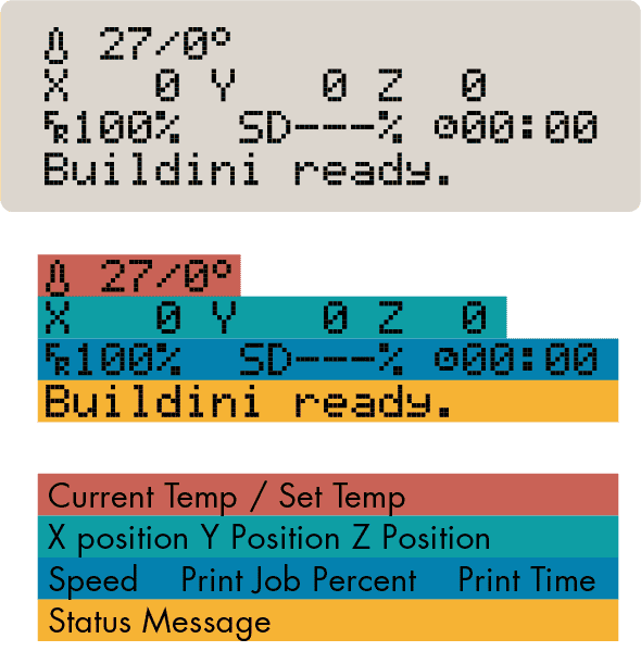 Diagram explaining LCD Info Screen
MAIN MENU
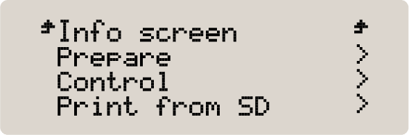 Image of LCD Main Menu
When the Printer is not printing and you push the Spin-N-Select Knob, you are taken from the Info Screen to the Main Menu. From this screen you can navigate to the sub-menus containing the Printer’s primary operations.
The two items that you will use from this list arePrepare and Print from SD.
PREPARE + ACTIVE PRINT MENUS
The two sub-menus you will use most frequently on your Buildini™ 3D Printer are the Prepare Menu and the Active Print Menu.
The Prepare Menu is accessible from the Main Menu when the Buildini™ is not 3D printing and has all of the operations needed to prep your Buildini™ for 3D printing.
During a print however, an Active Print Menu replaces the Main Menu. The Active Print Menu has the settings and operations needed during a print, such as the ability to pause a print.
PREPARE MENU
- Move Axis
- Auto Home
- Home X
- Home Y
- Home Z
- Disable Steppers
- Preheat PLA
- Preheat PETG
ACTIVE PRINT MENU
- Tune
- >Speed
- > Nozzle
- > Fan Speed
- > Flow
- Change Filament
- Pause Print
- Stop Print
IMPORTANT NOTE
Settings in the menu not mentioned in the guide are not used for regular operation. You should not change any of the unmentioned settings.
RESET BUTTON, USB PORT, & SD SLOT
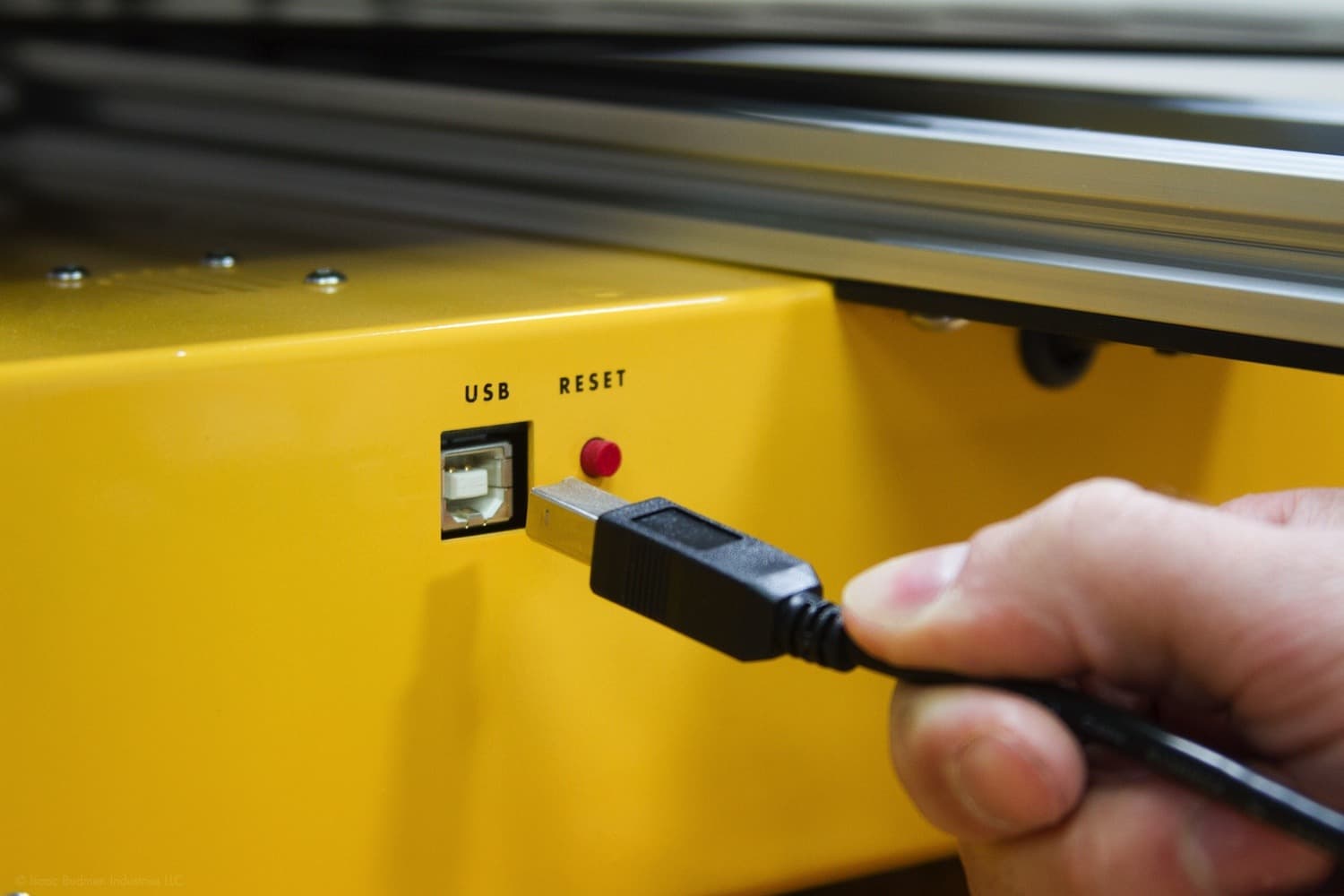 Image of the USB cable plugged in to Buildini™
The USB port is where you can connect your computer to control the Printer.
The reset button equates to shutting off the Buildini™ power. It is useful only when the Printer needs immediate cancellation.
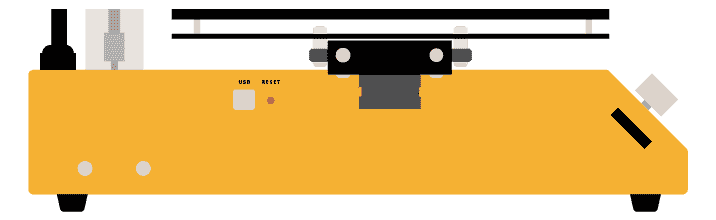 Diagram of left side of Buildini™ showing USB Port, Reset Button, and SD Slot
The SD Slot allows you to insert a memory card into the Buildini™. SD cards are used to run print jobs.
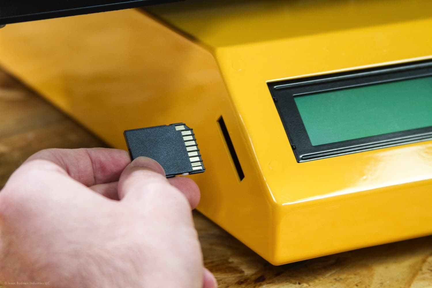 Image of SD Card inserted into Buildini™
IMPORTANT NOTE
Overuse of the reset button will improperly shut off the Printer and cause issues with the circuit board inside. The correct way of shutting off the Printer is to bring the temperature of the nozzle to at least 35 degrees Celsius and then shut it off using the power switch .
DOWNUP DIAL
The DownUp Dial is located at the top of the Z axis on the Buildini™. It allows manual height adjustments up or down by spinning it.
 Diagram of DownUp Dial
Use the DownUp Dial to manually adjust the Z axis and to prevent damage to the lift screw.
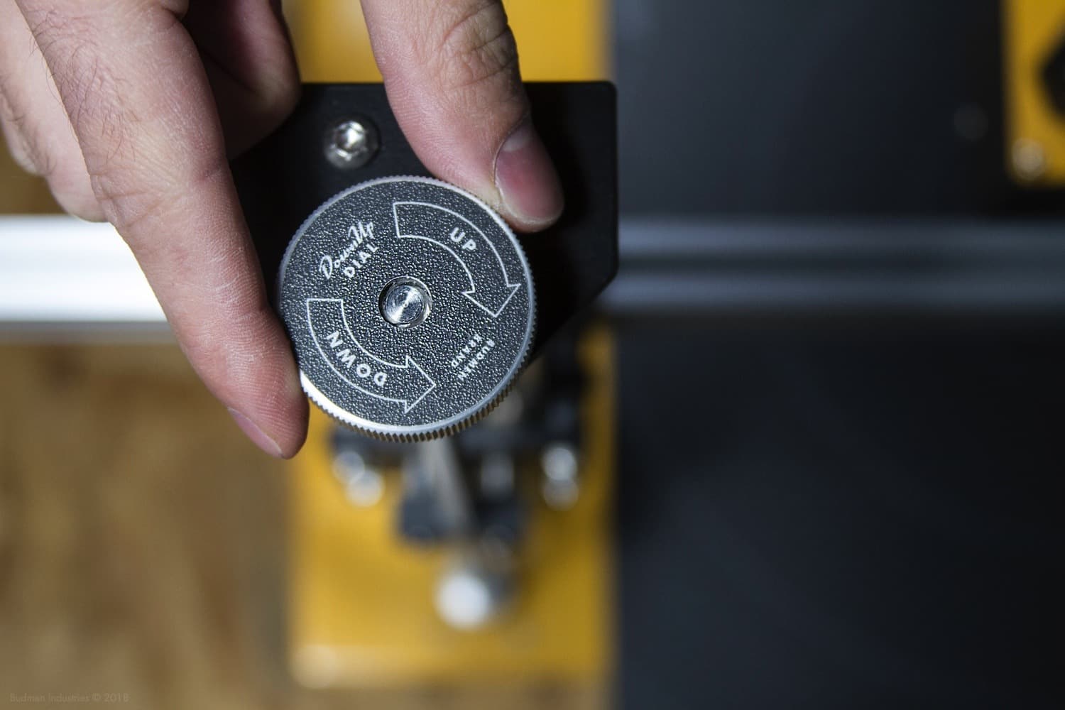 Image of fingers turning DownUp Dial

PRO-TIP
At the start of a print, if you notice the nozzle is slightly too close or too far from the platform, give the DownUp Dial a small turn to bring the nozzle to the right height. Only do this if your build platform is level.
Be careful not to touch the nozzle to the build platform, as it may cause damage.